I2C
I2C stands for Inter-Integrated Circuit. It is a bus interface connection protocol incorporated into devices for serial communication. It was originally designed by Philips Semiconductor in 1982. Recently, it is a widely used protocol for short-distance communication. It is also known as Two Wired Interface(TWI).
I2C Pinouts
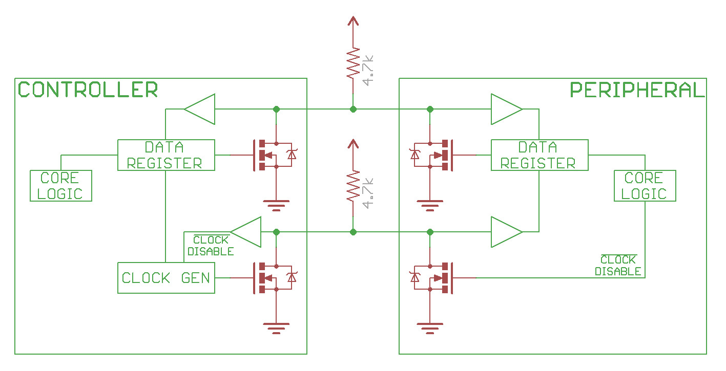
- SCL (Serial Clock): It carries the clock signal.
- SDA (serial data): Transfer of data takes place through this pin.
I2C Address
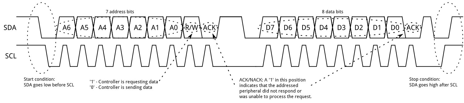
- Address Frame: 7 address bits + 1 Read/Write bit + 1 ACK/NACK.
- Data Frames: 8 data bits + 1 ACK/NACK following the successful transmission of the address frame.
I2C Protocol
- START: To initiate the address frame, the controller device leaves SCL high and pulls SDA low.
- STOP: Stop conditions are defined by a 0->1 (low to high) transition on SDA after a 0->1 transition on SCL, with SCL remaining high. During normal data writing operation, the value on SDA should not change when SCL is high, to avoid false stop conditions.
- ACK (acknowledge): Once the first 8 bits of the frame are sent, the receiving device is given control over SDA. If the receiving device does not pull the SDA line low before the 9th clock pulse, it can be inferred that the receiving device either did not receive the data or did not know how to parse the message. In that case, the exchange halts, and it's up to the controller of the system to decide how to proceed.
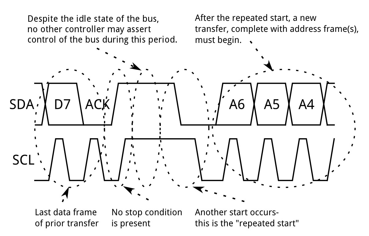
- Repeated Start: To perform a repeated start, SDA is allowed to go high while SCL is low, SCL is allowed to go high, and then SDA is brought low again while SCL is high. Because there was no stop condition on the bus, the previous communication wasn't truly completed and the current controller maintains control of the bus.
- Clock Streching: The clock is stretched when the slave device is not ready to accept more data by holding the SCL line low, hence disabling the master to raise the clock line. Master will not be able to raise the clock line because the wires are AND wired and wait until the slave releases the SCL line to show it is ready to transfer next bit.

Pull-up Resistance
- Low-level output voltage, Low-level output current, Rise time of both SDA and SCL signals, Capacitive load for each bus line
Min resistance gives the shortest rise time.
Max resistance provides the longest capable rise time.
Advantages
- Can be configured in multi-master mode.
- Complexity is reduced because it uses only 2 bi-directional lines (unlike SPI Communication).
- Cost-efficient.
- It uses ACK/NACK feature due to which it has improved error handling capabilities.
Limitaions
- Slower speed.
- Half-duplex communication is used in the I2C communication protocol.